Huiyao Laser
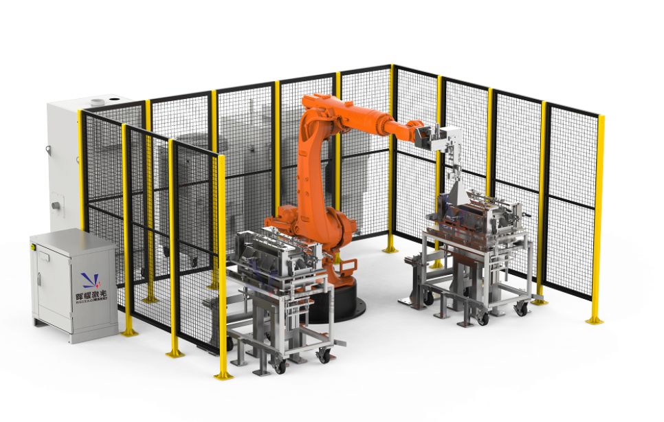
Prismatic BESS Battery Module Assembly Line
Prismatic BESS Battery Module Assembly Line
Couldn't load pickup availability
The prismatic BESS module assembly line is a precision-driven process that transforms individual lithium-ion cells into high-capacity energy blocks in form of battery module and pack. These lines typically feature high degree automation and manufacturing intelligence to ensure the structural integrity and electrical reliability required for stationary energy storage applications.
1. Cell Preparation and Testing
The process begins with OCV (Open Circuit Voltage) and internal resistance testing to ensure all cells in a module are closely matched.
2. Insulation Pad Installation
The installation of insulation pads (often referred to as expansion foam or compression pads) is a critical thermal and mechanical management step in BESS module assembly. These pads, typically made of specialized materials like ethylene propylene diene monomer (EPDM) or aerogel, are placed between individual prismatic cells.
3. Module Compression, Stacking and Bracing
Prismatic cells expand and contract during charge cycles. To maintain longevity, the cell stack is stacked and compressed under specific force (often several kilonewtons) secured using end plates and side straps. These are typically joined using Laser Welding or high-strength structural adhesives to create a rigid "box" frame.
4. Cell Terminal Pole Photography
In a BESS module assembly line, cell terminal pole photography is a high-speed vision inspection step that occurs immediately before the busbar welding process. This "intelligent eye" ensures that the electrical interconnections are perfectly aligned, which is critical for the long-term safety of high-capacity battery packs.
5. Laser Cleaning
In prismatic BESS module assembly, laser cleaning is a non-contact, high-precision surface preparation step that occurs immediately before busbar welding. It uses a high-intensity fiber laser to ablate (vaporize) microscopic contaminants from the cell terminal poles and busbar contact points.
6. CCS (Cell Contact System) Interconnection
The CCS interconnection is the stage where the "nervous system" of the battery is integrated. The CCS is a pre-integrated assembly typically consisting of a plastic carrier, busbars, and a flexible printed circuit (FPC) or wiring harness for sensing.
- CCS Placement: Copper or aluminum busbars are positioned across the cell terminals.
- Laser Welding: Lasers weld the busbars to the terminals. This requires extreme precision to ensure low contact resistance without damaging the cell's internal chemistry through excess heat.
7. Final Testing (EOL)
The finished module passes through an End-of-Line (EOL) station where it undergoes:
- Hipot Testing: Ensuring there are no electrical leaks between the high-voltage circuit and the module frame.
- Communication Check: Verifying the BMS can accurately read all cell data.
- Charge/Discharge Pulse: A brief functional test to confirm the integrity of all weld points.